
At F. D. Hurka Metrology, we work with manufacturers across the Southeast who face a recurring challenge: getting reliable data from surfaces that resist standard measurement approaches. Curved bores, rough castings, soft alloys, and fine-machined sealing faces all behave differently under a stylus or probe. Knowing how to measure roughness and how to verify your equipment is giving you the right numbers is what separates compliant production from costly rework.
This guide covers the tools, units, and calibration practices you need to measure hard-to-measure surfaces accurately. We also explain how our team supports manufacturers in automotive, aerospace, and general precision manufacturing with traceable, accredited calibration services backed by more than five decades of hands-on metrology work.
What Is Surface Texture and Why Is It Difficult to Measure?
Surface texture is the combination of roughness, waviness, and lay that defines the topography of a machined or formed surface.
Roughness refers to the short-interval peaks and valleys left by a machining process. Waviness covers broader, repeating undulations. Lay describes the direction of those patterns. Together, these three elements determine how a surface performs under friction, load, corrosion, and sealing conditions.
Measurement becomes difficult when surfaces combine these characteristics in unpredictable ways. A sand-cast housing, for example, carries a non-directional, random texture that stylus profilometers struggle to characterize consistently. A honed cylinder bore may have a cross-hatch lay that looks smooth in one direction and rough in another.
The instrument, the cutoff wavelength, the stylus tip radius, and the sampling length all influence what you read. That is why selecting the right surface texture measurement equipment and calibrating it properly matters before you ever touch a part.
How to Measure Surface Roughness: Instruments and Methods
Surface roughness is measured by traversing a calibrated stylus or optical probe across a surface and recording the height deviations from a mean line.
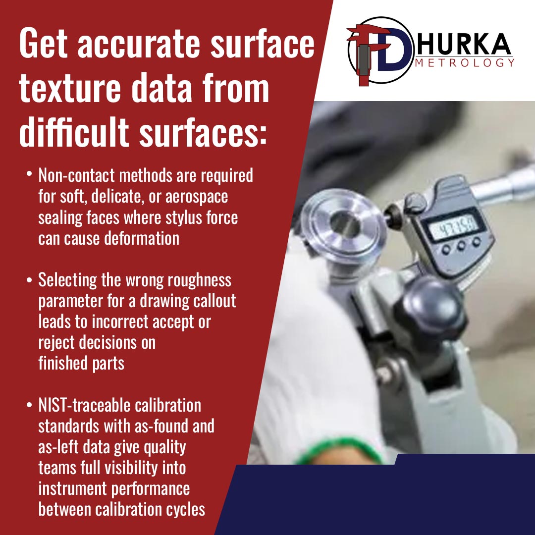
The most common instrument is the contact profilometer, which drags a diamond stylus across the surface at a controlled speed and force. The vertical motion of the stylus is recorded, filtered, and converted into parameter values. Non-contact methods, including laser confocal microscopy and white-light interferometry, are used when the surface is too soft, too small, or too delicate for stylus contact.
Knowing how to measure surface roughness correctly means matching the instrument to the surface type. Here are three measurement scenarios we regularly see at F. D. Hurka Metrology:
- Scenario 1: Automotive cylinder liners. These surfaces require plateau honing with a defined Ra and Rz. A contact profilometer with a 0.8 mm cutoff wavelength is standard, but the bearing ratio curve (Rmr) is often equally important for oil retention. A single Ra reading is not enough.
- Scenario 2: Aerospace sealing faces. Flatness and roughness requirements are tight. Non-contact methods are preferred because the stylus force can deform the surface. The measurement area must be representative of the full seating zone, not just one pass.
- Scenario 3: Powder-coated or anodized aluminum panels. Coating layers change the texture profile from the base metal. Measurements taken before and after coating must be compared against the correct surface texture standard to determine if the part meets drawing requirements.
In each case, the method must match the surface. Applying the wrong instrument or the wrong cutoff wavelength produces data that does not reflect the part’s actual functional performance.
Surface Roughness Measurement Units Explained
Surface roughness measurement units in the U.S. are typically expressed in microinches (µin), while international standards use micrometers (µm).
One micrometer equals 39.37 microinches. Many drawings produced for global customers show both units, for example, “0.8 µm (32 µin).” The two systems are interchangeable for Ra reporting purposes.
The most common parameters you will encounter are:
| Parameter | Full Name | Description |
| Ra | Roughness Average | The arithmetic average of absolute profile height deviations from the mean line, as defined in ASME B46.1. The most widely used parameter in U.S. manufacturing. |
| Rz | Average Maximum Height | The mean of the five largest peak-to-valley distances within a sampling length. More sensitive to surface defects than Ra. |
| Rq | Root Mean Square Roughness | Similar to Ra but mathematically weighted toward extreme peaks and valleys. |
| RSm | Mean Spacing of Profile Elements | Measures how closely spaced the peaks are, which matters for sealing and coating adhesion. |
According to ASME B46.1-2019, Ra is formally defined as “the arithmetic average of the absolute values of the profile height deviations from the mean line, recorded within the evaluation length.” This standard also defines waviness and lay parameters, covering the full scope of surface texture measurement.
Understanding which parameter applies to your application prevents misinterpretation of print callouts. An aerospace drawing specifying Rz 6.3 µm is not interchangeable with an Ra 6.3 µm requirement. The two values describe different aspects of the surface.
What Is a Surface Roughness Calibration Standard?
A surface roughness calibration standard is a physical reference specimen with certified parameter values used to verify that a profilometer or surface texture instrument is reading correctly.
Calibration results for common roughness parameters can be made traceable to NIST (National Institute of Standards and Technology), which describes surface roughness and step height calibration methods and uncertainty budgets for parameters such as Ra, Rq, Rz, Rt, Rp, Rv, and RSm.
A calibration standard often consists of a hardened block with a defined profile (such as grooves or a sinusoidal pattern) and an accompanying certificate showing the certified values and traceability. NIST SRM 2075, for example, is a sinusoidal roughness specimen certified for profile roughness average (Pa) and spatial wavelength, intended for calibrating stylus instruments.
As part of ISO/IEC 17025-aligned practice, F. D. Hurka Company uses calibrated reference specimens when verifying surface texture measurement equipment.
How to Measure Roughness on Difficult Surfaces
Not all surfaces respond the same way to a profilometer stylus. Here is how to approach four common problem areas:
- Curved or cylindrical surfaces. Standard profilometer skids are designed for flat surfaces. On bores or curved ODs, you need a radius-corrected skid or a skidless instrument with form removal software. The cutoff wavelength selection must account for the part’s curvature radius to avoid confusing form error with waviness.
- Soft materials (copper, aluminum, lead alloys). Stylus contact force as low as 0.75 mN can mark a soft surface. Use a profilometer with adjustable force, or switch to a non-contact optical method. Repeat measurements at the same location on soft surfaces can produce progressively smoother readings due to burnishing.
- Textured coatings and thermal spray. These surfaces carry high Ra values with irregular profiles. A longer evaluation length captures the true character of the texture. Compare your surface texture standard against similar reference specimens to avoid over-reading due to outlier peaks.
- Rough castings and sintered parts. ASME B46.1 notes that casting surfaces have random, non-directional deviations and should not be evaluated the same way as machined surfaces. Visual and tactile comparison to a calibrated surface texture standard is often the appropriate method, rather than a single profilometer trace.
Selecting the Right Surface Texture Measurement Equipment
The right surface texture measurement equipment depends on the parameter being measured, the surface geometry, and the required measurement uncertainty.
Key selection factors:
- Contact vs. non-contact. Contact profilometers are accurate and portable, but can damage soft or micro-featured surfaces. Non-contact instruments handle delicate, steep, or optically complex surfaces without risk.
- Cutoff wavelength (λc). ASME B46.1 and ISO 4288 both provide tables linking the Ra range to the appropriate λc. Selecting the wrong cutoff wavelength changes what the instrument classifies as roughness vs. waviness.
- Stylus tip radius. A 2 µm tip radius reads finer features than a 5 µm tip. NIST research has shown that tip size affects measured Ra on surfaces with rectangular profiles, with larger tips consistently reading lower values.
- Calibration status. A surface texture instrument that has not been verified against a traceable surface roughness calibration standard cannot be trusted for production decisions.
At F. D. Hurka Metrology, we help customers select instruments from our precision measurement equipment lines and confirm calibration status before inspection results are used for acceptance decisions.
Why NIST-Traceable Calibration Matters for Surface Texture
When your surface texture measurement equipment drifts, you may be accepting parts that do not meet drawing requirements or rejecting parts that do. Both outcomes cost money.
ISO/IEC 17025-accredited calibration connects every measurement to NIST through a documented chain of comparisons. That chain protects you during customer audits, internal quality reviews, and regulatory inspections.
Our calibration intervals are set based on equipment type, use frequency, and manufacturer recommendations. We issue calibration certificates with as-found and as-left data, giving you visibility into how your instrument has been performing between calibration cycles.
Surface roughness calibration is not a one-time event. Stylus tips wear. Environmental conditions shift instrument baselines. The surface roughness calibration standard used to verify your profilometer should itself be re-certified on a defined schedule to maintain traceability.
Surface Roughness FAQs from the Shop Floor
Surface texture questions come up often on the shop floor and in the quality lab. Below are the questions our team at F. D. Hurka Metrology hears most frequently, along with direct answers to help you make better measurement decisions.
Q: What is the difference between Ra and Rz?
Ra is the arithmetic average of all profile height deviations. Rz is the mean of the five largest peak-to-valley heights. Rz is more sensitive to surface defects and is preferred in applications where a single deep scratch would cause functional failure.
Q: Can I use the same profilometer for both flat and curved surfaces?
Not always. Curved surfaces require skid correction or skidless measurement modes. Confirm your instrument’s capability and confirm that the instrument is calibrated for the geometry you are measuring.
Q: How often should surface texture measurement equipment be calibrated?
Calibration frequency depends on instrument type, environment, and how often the equipment is used. At a minimum, calibrate annually and whenever the instrument is moved, repaired, or gives suspect readings. Check your surface roughness calibration standard against a certified reference before any critical inspection run.
Q: What surface texture standard applies to my industry?
ASME B46.1 is the primary U.S. standard. ISO 4287 and ISO 4288 govern international applications. Automotive manufacturers often reference additional OEM-specific surface callouts that go beyond Ra and require Rk or Rmr parameters.
Work with F. D. Hurka Metrology
F. D. Hurka Metrology in Charlotte, NC, has supported precision manufacturers across nine Southeastern states since 1970. Our ISO/IEC 17025 accreditation covers a broad scope of dimensional and surface measurement services. We offer a 3 to 5-day calibration turnaround for most instruments, including surface texture measurement equipment, at competitive pricing.
If your team is dealing with hard-to-measure surfaces and needs calibrated instruments, traceable reference standards, or technical guidance on measurement method selection, start by clicking on our Contact Page to connect with our team.

Chuck Meredith is a military veteran with over two decades of experience at FD Hurka Metrology. Since joining the company in 1999, Chuck dedicated 20 years to sales before stepping into the role of President in January 2020. Passionate about people and service, Chuck takes pride in ensuring FD Hurka provides exceptional gaging and calibration solutions to its customers.
GET IN TOUCH
Shipping Address
Mailing Address
Phone Number
Fax Number
CONTACT
To request specific information or to have someone from the F. D. Hurka Metrology contact you, please fill out the contact form or click the button below to request a quote: