
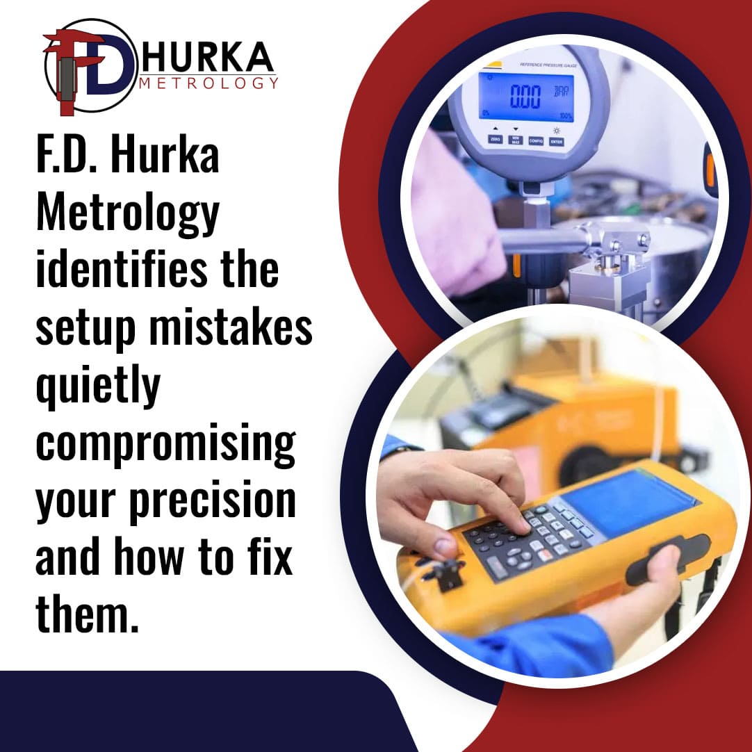
Video measurement systems are designed to deliver fast, accurate, and repeatable results, but only when the setup is right. A small mistake in lighting, calibration, positioning, or software configuration can quietly introduce errors that affect part quality, tolerance verification, and compliance. Also known as vision measurement machines or vision measurement systems, these non-contact optical tools are widely used in precision manufacturing, medical device production, and aerospace inspection.
At F. D. Hurka Metrology in Charlotte, North Carolina, we work with manufacturers across the Southeast who rely on non-contact optical measurement as part of their quality programs. We have seen how setup issues can go unnoticed while steadily undermining accuracy. This article highlights the most common mistakes and what to do instead.
What Is a Vision Measurement System?
A vision measurement system (VMS) combines a high-resolution camera, precision stage, adjustable lighting, and measurement software. Together, these components capture detailed images of a part and calculate precise dimensional data from those images. Unlike contact methods such as calipers or probes, the system measures without touching the part.
This makes a video measurement system especially valuable for:
- Small, delicate, or soft parts that could be deformed by contact
- High-feature-count parts requiring many measurements quickly
- Components with complex 2D profiles, angles, or edge geometry
The trade-off is that non-contact optical systems are more sensitive to setup conditions. Lighting, part placement, calibration, and environment all directly affect what the camera sees and how accurately the software interprets it.
Why Setup Conditions Matter More Than You Think
The Non-Contact Advantage Creates New Dependencies
Contact tools like calipers and micrometers measure what they physically touch. A vision measurement machine measures what the camera sees and what the software interprets. That shift introduces a new set of variables. The optical path, the environment, and the calibration state of the system all become part of the measurement. Get any of them wrong, and the numbers will be wrong too.
Understanding these dependencies is the first step to avoiding costly setup errors.
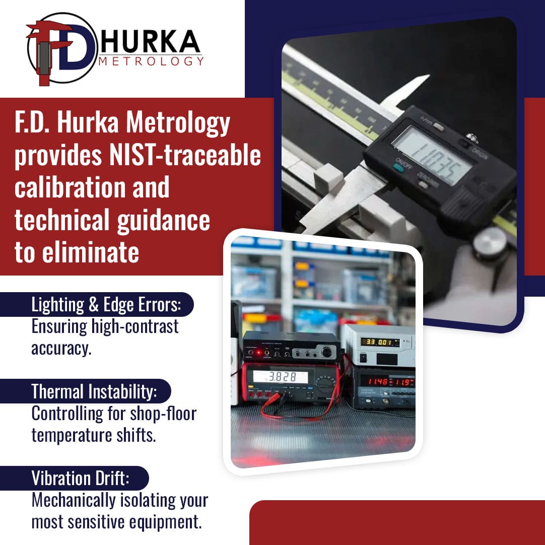
Mistake 1: Poor Lighting Setup
The most common video measurement system mistake is incorrect or inconsistent lighting.
Lighting in a vision measurement machine serves one purpose: to create contrast. The higher the contrast between a part edge and its background, the more accurately the software can locate that edge. Low contrast leads to poor edge detection, which leads to measurement errors.
Common lighting mistakes include:
- Oversaturation: Too much light washes out edge detail. The software loses the edge profile and cannot find a reliable measurement point.
- Underexposure: Too little light creates noise. Noisy images produce inconsistent edge locations.
- Inconsistent illumination: Uneven lighting casts shadows across the part. Those shadows appear to the camera as false edges.
- Wrong light type for the part: Shiny, reflective, or chamfered parts require specific lighting angles. A chamfered edge lit from the wrong direction can produce two apparent edges instead of one, causing the software to select the wrong measurement point.
The fix is to set the lighting so that the camera captures a full range of gray-scale values without clipping at either the bright or dark end. Test the setup on each part type, and document the lighting settings so results are repeatable shift to shift.
Mistake 2: Unstable or Vibrating Setup Surface
A vision measurement machine placed on a vibrating or unstable surface produces random measurement errors that cannot be corrected by software.
These are called random errors. They differ from systematic errors, which follow a predictable pattern and can sometimes be corrected. Random errors from vibration or movement appear as inconsistent readings that shift unpredictably between measurements.
Sources of surface instability include:
- Nearby machine tools or presses transmitting vibration through the floor
- Air handling units, creating low-frequency vibration
- Tables or stands that flex under the weight of the system
- Direct sunlight or HVAC airflow – causing thermal gradients at the measurement surface
Place the vision measurement system on a stable, isolated surface. Many manufacturers use granite surface plates or vibration-dampening mounts. Keep the system away from high-vibration equipment. If the floor itself is a source of vibration, isolation pads are worth the investment.
Mistake 3: Thermal Instability in the Measurement Environment
Temperature changes directly affect the mechanical components of a video measurement system, causing dimensional shifts that translate into measurement errors.
Metal components expand and contract with temperature. When the system or the parts being measured change temperature between readings, the measurements change too. This is called thermal expansion error, and it is one of the more difficult errors to diagnose because it builds gradually.
Temperature also affects the electrical parameters of the system. Sensors experience what is called temperature zero drift, where the baseline reference shifts as temperature changes, without any change to the part being measured.
Best practices for thermal stability:
- Operate the system in a temperature-controlled room, ideally at a stable 20°C (68°F)
- Allow both the system and parts to acclimate to room temperature before measuring
- Avoid placing the system near doors, windows, or HVAC vents
- Monitor and log room temperature as part of your measurement records
For manufacturers in the Southeastern U.S., where ambient temperatures and humidity can vary widely, a dedicated temperature-controlled metrology lab is often the most reliable solution.
Mistake 4: Skipping or Delaying Vision System Calibration
What Calibration Actually Does in a Vision System
Calibration in a vision measurement system is not a general tune-up. It is a specific process that maps the camera’s pixel coordinates to real-world dimensional units. It also ties those units to a recognized measurement standard through a documented chain of traceability. Without that chain, the measurements have no verifiable basis.
An uncalibrated or overdue-for-calibration vision measurement machine produces results that cannot be trusted or used for compliance documentation.
Calibration is the process that maps the camera’s pixel coordinates to real-world dimensional units. Without calibration, the software measures in pixels only. Pixel measurements have no traceable value to any recognized standard.
More specifically, calibration ties the system’s measurements back to recognized standards. In the United States, those standards are maintained by the National Institute of Standards and Technology (NIST). According to NIST, calibration services are designed to help makers and users of precision instruments achieve the highest possible levels of measurement quality and productivity.
For manufacturers operating under ISO 9001 or ISO/IEC 17025, ISO Section 7.1.5.2 requires that measuring equipment be calibrated at specified intervals against measurement standards traceable to national or international standards. Skipping scheduled calibration is a direct compliance gap.
Common calibration mistakes include:
- No calibration on initial setup: The system ships calibrated from the factory, but transportation and installation affect that calibration. Always perform a calibration check before the first use at a new location.
- Overextended calibration intervals: Calibration intervals should be based on how the system is used, how stable its environment is, and what your quality program requires. Many manufacturers default to annual calibration, but should reassess based on usage.
- Calibration without addressing random errors first: If the system has loose components, encoder issues, or vibration problems, calibration will not fix those. Random errors must be resolved mechanically before calibration can be meaningful.
F. D. Hurka Metrology provides ISO/IEC 17025 accredited calibration services for precision measurement instruments, with traceability to NIST. We help manufacturers document and maintain calibration records that satisfy audit requirements.
Mistake 5: Improper Part Fixturing
Parts that are not secured properly move during measurement. Movement during imaging produces blurry or misregistered images, which lead to incorrect dimensional data.
This mistake is more common than it sounds. Operators often place parts on the stage by hand and assume the part will stay still during measurement. Lightweight or irregular parts can shift slightly when the stage moves, especially on systems with motorized axes.
The result is measurement inconsistency that looks like a system error but is actually a part-handling problem.
Proper fixturing practices:
- Use fixture plates, clamps, or vacuum holders appropriate to the part geometry
- Verify that the fixture does not obstruct any features to be measured
- Check that the part is level with the measurement plane (perpendicular to the optical axis)
- Document and reuse the same fixture setup for repeated measurement of the same part
For parts with features that require multiple orientations, plan the sequence before measuring. Disturbing the part mid-sequence resets the registration and can invalidate previous measurements.
Mistake 6: Ignoring Lens Distortion
All optical lenses introduce some level of geometric distortion. Failing to account for this in setup or software configuration leads to systematic measurement errors, especially near the edges of the field of view.
Lens distortion types include radial distortion (where lines bow inward or outward from the center) and eccentric distortion (where the optical center is offset). Both introduce errors when measuring features located away from the center of the image.
Using a high-quality telecentric lens reduces but does not eliminate distortion. The measurement software must be configured to apply a distortion correction model based on the specific lens in use. If the correction model is outdated or was applied for a different lens, the distortion compensation will be wrong.
What to check:
- Confirm that the software’s distortion correction is matched to the current lens
- Perform a calibration artifact measurement that covers the full field of view, not just the center
- Measure critical features near the center of the field of view when sub-micron accuracy is required
The Role of Vision System Calibration Standards
Meeting vision system calibration standards means more than running a calibration routine. It means documenting a traceable chain from your measurement results back to recognized national standards.
Under ISO/IEC 17025, calibration laboratories must verify measurement uncertainties, review procedures regularly, and perform quality checks on all systems. Accreditation requires the lab to be evaluated annually and to publish its scope of calibration capabilities.
For manufacturers in Charlotte and across the Southeast, F. D. Hurka Metrology holds ISO/IEC 17025 accreditation. Our calibration services are NIST-traceable, and we provide the documentation your quality team needs for internal audits, customer audits, and regulatory reviews.
Protecting Your Measurement Investment in Charlotte and the Southeast
A vision measurement system is a significant investment. Setup mistakes erode that investment quietly by producing data that cannot be trusted. The consequences range from failed audits to escaped defects to product recalls.
The six mistakes covered here, including poor lighting, surface instability, thermal drift, overdue calibration, improper fixturing, and lens distortion errors, are all preventable. Each one has a documented cause and a practical fix.
F. D. Hurka Company has served precision manufacturers in Charlotte, North Carolina, and across nine Southeastern states since 1972. Our ISO/IEC 17025 accredited calibration services, combined with our product expertise in Micro-Vu vision systems, give manufacturers the support they need to get setup right and keep it right.
Click on to our contact page to discuss your vision system calibration and setup needs.

Chuck Meredith is a military veteran with over two decades of experience at FD Hurka Metrology. Since joining the company in 1999, Chuck dedicated 20 years to sales before stepping into the role of President in January 2020. Passionate about people and service, Chuck takes pride in ensuring FD Hurka provides exceptional gaging and calibration solutions to its customers.
GET IN TOUCH
Shipping Address
Mailing Address
Phone Number
Fax Number
CONTACT
To request specific information or to have someone from the F. D. Hurka Metrology contact you, please fill out the contact form or click the button below to request a quote: