
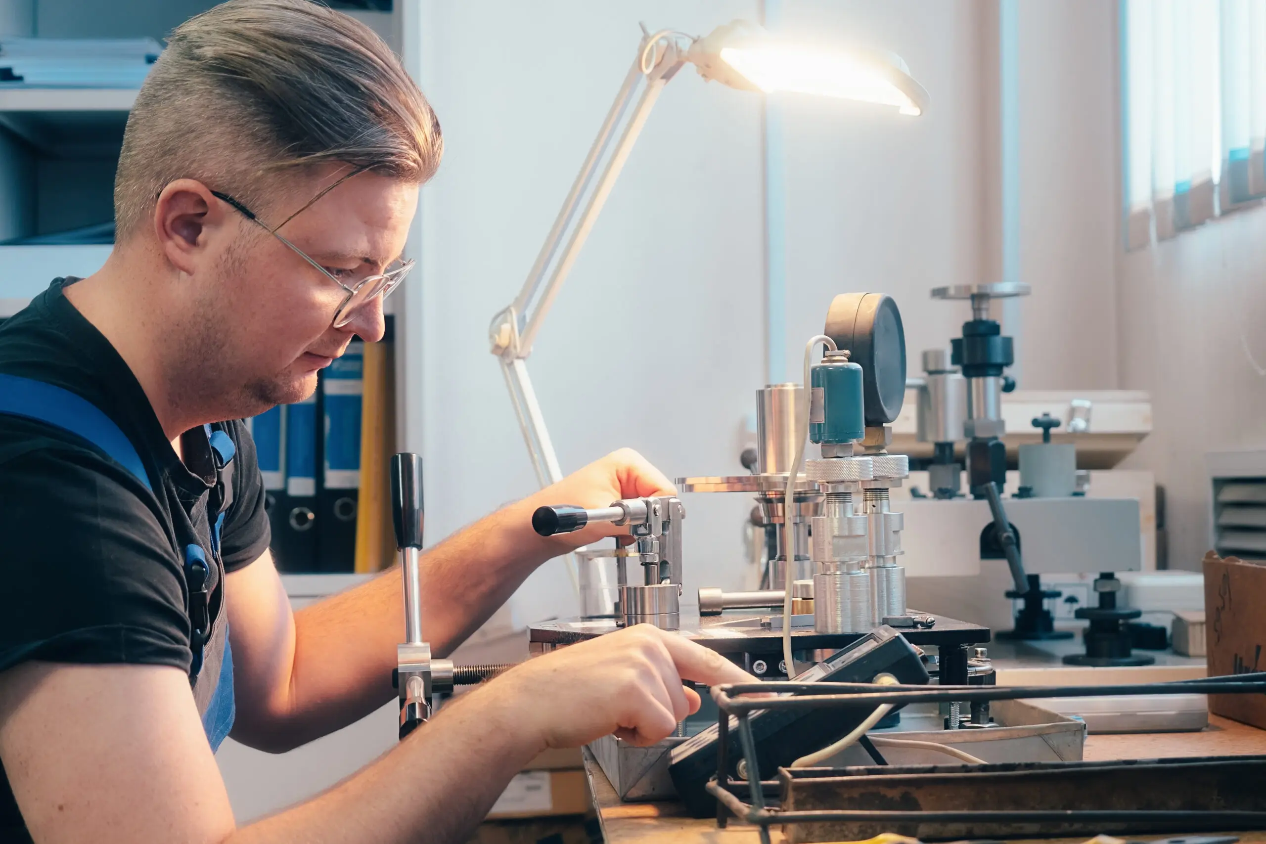
When manufacturers rely on optical inspection, one of the most important topics to understand is vision system calibration. A vision system can measure edges, distances, diameters, angles, locations, and profiles without touching the part, but accurate results do not happen automatically. They depend on how well the system is calibrated, how stable the setup remains, and how consistently the system is used.
That is why vision system calibration should be treated as a core measurement requirement rather than a simple maintenance task. A machine may power on, capture clear images, and still deliver measurement results that drift from true values if the optics, stage, focus, scale relationship, or environmental conditions are not properly controlled. Accurate measurement requires a complete approach that connects the machine, the software, the calibration artifact, the measuring environment, and the user’s procedures.
This matters for any facility using optical metrology for dimensional inspection. According to Mitutoyo, ISO 10360-7:2011 is the first international standard specifically addressing the calibration and testing of non-contact coordinate measuring machines equipped with imaging probing systems, including video and vision measuring instruments. That matters because it shows vision systems are not being treated as informal inspection devices. They fall within recognized metrology expectations for acceptance and reverification.
For companies seeking calibration support, at F. D. Hurka Metrology, we provide both in-house and on-site calibration services for precise measurement instruments, operate a temperature- and humidity-controlled laboratory, are certified to ISO 17025:2017 standards, and have an A2LA Scope of Accreditation. F. D. Hurka also notes that its contract inspection lab can support part measurement by CMM, vision system, or hand tools, and that it offers support and training services as well.
 Why Vision Systems Need Formal Calibration
A vision system measures by interpreting images. That means measurement accuracy depends on more than one component. The machine must know how pixels relate to real dimensions. The optical path must be properly characterized. The focus position must be stable. The stage must move accurately. The software must detect edges consistently. The lighting must reveal the true feature instead of creating misleading contrast.
In other words, vision system calibration is not just about checking one number on a certificate. It is about confirming that the entire measurement chain is working together correctly. NIST’s traceability policy explains that metrological traceability requires a documented, unbroken chain of calibrations to specified reference standards, with each step contributing to measurement uncertainty. That principle applies directly to optical measurement systems: the result needs to connect back to known references in a controlled and documented way.
Traceability Is a Basic Requirement
One of the most important requirements in vision system calibration is traceability. A measurement result is much more useful when the facility can show how that result connects to recognized reference standards. Without traceability, numbers may look precise on the screen, but confidence in those numbers is weaker.
Traceability is especially important in quality systems, customer-driven inspection environments, and regulated industries. It supports consistency between operators, systems, locations, and time periods. It also helps facilities interpret whether a measurement result is fit for purpose rather than simply convenient.
This is why a good vision calibration process should include documented standards, defined artifacts, controlled procedures, and records that show what was calibrated, when, by whom, under what conditions, and against which reference. NIST specifically defines metrological traceability as the property of a result that can be related to a reference through a documented unbroken chain of calibrations, each contributing to uncertainty.
Calibration Must Address the Optical System
The optical portion of the machine is central to vision system calibration. Unlike contact systems that physically touch a surface, vision systems depend on how the camera and lens interpret the part image. That creates several calibration needs.
Mitutoyo’s vision system documentation states that a calibration chart is used to compensate for pixel size, autofocus accuracy, and optical axis offset at each magnification. Related Mitutoyo materials also note that compensation charts are used to correct distortions caused by the optical system. Those details show that a valid optical calibration is not limited to one master setting. It often needs to account for magnification-specific behavior and image-based measurement effects.
This has practical meaning in day-to-day measurement. If a system uses multiple magnifications, zoom positions, or lens configurations, calibration has to reflect that. A system can perform well at one setup and differently at another. For that reason, vision system calibration should verify the conditions under which the machine is actually used, not only a simplified reference case.
Focus and Z-Axis Behavior Matter
Accurate measurement in a vision system is not only about the X and Y image. Focus behavior matters too. If autofocus is not accurate, or if the focal plane shifts, the edge can appear differently and the measurement result can change. For systems measuring height or using focus-based routines, this becomes even more important.
Micro-Vu’s VF1 specifications state accuracy at the calibration plane and also list a different performance condition within a stated distance of that plane, while also specifying operation within 20.0°C ± 1°C at the focal point position and use of a calibration artifact. That combination reinforces an important calibration reality: performance can depend on where the measurement occurs relative to the calibration plane and under what conditions the system is operated.
So one key requirement in vision system calibration is understanding the measurement volume. Facilities should not assume that one calibration point automatically guarantees identical performance everywhere in the machine’s usable space.
Lighting Is Part of the Measurement System
Lighting is often underestimated, but it is one of the practical foundations of vision system calibration. A vision machine does not measure the physical edge directly. It measures the image of that edge. If the lighting changes the appearance of the feature, the reported measurement can change as well.
Keyence’s lighting resources describe illumination technique selection as important for improving inspection accuracy and efficiency, while its vision system materials emphasize stable imaging through the combination of cameras and lighting. Micro-Vu also describes its software and hardware in terms of imaging and lighting control for accurate measurements. Together, those sources support a straightforward conclusion: lighting is not just an accessory. It is part of the measuring process.
For that reason, vision system calibration requirements should include stable and repeatable illumination practices. The lighting setup used during measurement should be appropriate for the feature being evaluated, and the facility should avoid frequent uncontrolled changes that affect edge contrast or shadowing.
Stage Motion and Mechanical Geometry Must Be Verified
Even though vision systems are optical, their accuracy also depends on mechanical motion. The stage that carries the part or moves under the optics must position accurately and repeatably. Backlash, wear, alignment errors, and axis geometry problems can all affect results.
That is one reason standards such as ISO 10360-7 matter. They place imaging systems within a formal framework for acceptance and reverification testing rather than treating them as simple camera tools. In practice, this means vision system calibration should evaluate more than the camera image alone. It should also consider whether stage positioning and machine geometry support trustworthy dimensional results.
When facilities overlook this, they sometimes focus only on image clarity and forget that coordinate accuracy also depends on how the system moves.
Software, Edge Detection, and Measurement Strategy Need Control
Modern optical systems rely heavily on software. The machine does not simply display an image; it interprets that image using algorithms. Micro-Vu states that its software uses advanced edge detection algorithms and supports repeatable measurement processes with sub-pixel accuracy. That is useful capability, but it also highlights another requirement: software settings and edge-detection behavior must be controlled if measurement results are to remain consistent.
This means vision system calibration is closely tied to measurement strategy. Edge threshold settings, focus methods, feature construction methods, part orientation, and program logic can all influence the reported result. A facility should not treat calibration as separate from the program used to measure production parts. In many cases, the best practice is to review calibration and programmed measurement routines together.
Environmental Control Is Part of Vision System Calibration
Environmental conditions can strongly affect optical metrology. Temperature can change machine geometry, part size, and focal relationships. Vibration can influence image stability or stage performance. Dust can affect optics and stage surfaces. Airflow and unstable lighting conditions can make measurements less repeatable.
Micro-Vu’s published operating condition of 20.0°C ± 1°C at the focal point position is a reminder that optical systems are specified for controlled conditions, not unlimited shop-floor variability. At F. D. Hurka Metrology, we also emphasize that its in-house calibration laboratory is temperature and humidity-controlled, which reflects how important environmental stability is in precision calibration work.
So, a real vision system calibration requirement is not only a service event. It is also a facility condition. If the measurement environment drifts too far from the system’s intended operating range, calibration confidence can suffer.
Calibration Intervals Should Be Based on Risk and Stability
Another requirement for effective vision system calibration is choosing reasonable intervals. NIST states that it does not require one set recalibration interval for all measuring instruments or standards. Instead, interval decisions depend on factors such as customer accuracy requirements, contract or regulatory requirements, the inherent stability of the instrument, and environmental factors that may affect stability. NIST also recommends using internal measurement assurance practices and calibration history to refine intervals over time.
That guidance fits vision systems well. A machine used constantly in a production setting may need a different review schedule than a machine used less often in a controlled lab. A stable system with strong history may support one interval, while a system exposed to frequent setup changes, environmental shifts, or heavy use may justify closer monitoring.
This is why vision system calibration should be part of a broader calibration schedule rather than handled informally.
Operators and Procedures Matter More Than Many Facilities Expect
Even a well-calibrated machine can produce poor results if the procedure is inconsistent. Part placement, fixture stability, lighting selection, focus method, cleaning practices, and measurement program choice all influence the final number.
At F. D. Hurka Metrology, we offer support and training services for precision measurement equipment. That is a useful reminder that training is not separate from calibration quality. In optical metrology, user understanding often determines whether the calibrated system is used in a way that preserves its performance.
For many facilities, one overlooked requirement in vision system calibration is operator discipline. Calibration supports the system, but procedures support the result.
 What an Effective Calibration Program Should Include
 What an Effective Calibration Program Should Include
A strong vision system calibration program should usually include several elements working together:
- documented traceability to appropriate reference standards
- calibration artifacts suited to the optical system and magnification range
- verification of pixel scaling, autofocus performance, and optical axis behavior
- evaluation of stage motion and usable measuring volume
- stable environmental conditions during calibration and use
- controlled lighting and repeatable imaging practices
- documented software and program settings for critical measurements
- defined recalibration intervals based on risk, use, and stability
- training for operators and reviewers
- clear records for audits, customer requirements, and internal quality control
The exact details will vary by machine and application, but the overall idea is consistent: vision system calibration must support the full measurement process, not just one isolated machine check.
FD Hurka: Your Trusted Partner
And for businesses that need outside support, at F. D. Hurka Metrology, we provide in-house and on-site calibration services, a temperature- and humidity-controlled ISO 17025:2017 laboratory with A2LA accreditation, contract inspection capabilities including vision systems, and support and training services.
Common FAQs
-
What is vision system calibration?
Vision system calibration is the process of verifying and adjusting an optical measuring system so it can produce accurate and repeatable measurement results.
-
Why is vision system calibration important?
It is important because a vision system depends on optics, lighting, software, stage motion, and environmental stability to measure correctly. If any of these factors are off, results can become unreliable.
-
What are the main requirements for accurate vision system calibration?
The main requirements include traceability, optical verification, stable lighting, accurate stage motion, controlled software settings, environmental control, and documented procedures.
-
How does lighting affect a vision measuring system?
Lighting affects how edges and features appear in the image. Poor or inconsistent lighting can change the way the system detects part features and may lead to inaccurate measurements.
-
Does vision system calibration only involve the camera and lens?
No. Vision system calibration also involves stage movement, focus behavior, software settings, measurement routines, and the surrounding environment.
-
Why is traceability important in vision system calibration?
Traceability helps connect measurement results to recognized standards through documented calibration steps, which supports confidence in the accuracy of the results.
-
Can environmental conditions impact vision system calibration?
Yes. Temperature, vibration, dust, airflow, and other environmental conditions can affect machine stability, image quality, and measurement consistency.
-
How do software settings influence vision system measurements?
Software settings such as edge detection, focus methods, and measurement routines can affect how the system interprets features and reports final dimensions.
-
How often should a vision system be calibrated?
Calibration intervals should be based on how the system is used, the environment it operates in, the required measurement accuracy, and the system’s stability over time.
-
What makes a strong vision system calibration program?
A strong program includes traceable standards, regular verification, controlled lighting, stable environmental conditions, documented procedures, trained operators, and consistent recordkeeping.

Chuck Meredith is a military veteran with over two decades of experience at FD Hurka Metrology. Since joining the company in 1999, Chuck dedicated 20 years to sales before stepping into the role of President in January 2020. Passionate about people and service, Chuck takes pride in ensuring FD Hurka provides exceptional gaging and calibration solutions to its customers.
GET IN TOUCH
Shipping Address
Mailing Address
Phone Number
Fax Number
CONTACT
To request specific information or to have someone from the F. D. Hurka Metrology contact you, please fill out the contact form or click the button below to request a quote: